
Cervical Spine X-Ray Essentials
How to interpret cervical spine X-Rays
Introduction
The cervical spine is highly mobile yet vulnerable, and small injuries can have major consequences if overlooked. While CT is now the gold standard for assessment due to its superior sensitivity, plain radiographs remain widely used in many parts of the world. A solid grasp of cervical spine anatomy and a structured approach to reading X-rays therefore remain essential for safe and accurate interpretation.
General cervical spine anatomy
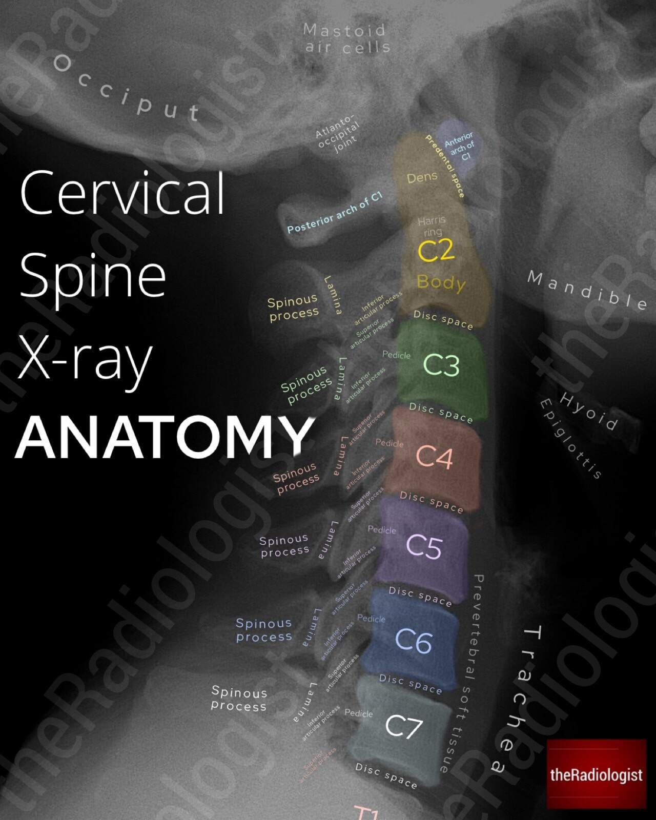
The cervical spine is composed of seven vertebrae (C1–C7), forming a highly mobile and structurally complex region that supports the skull, protects the spinal cord and vertebral arteries, and allows extensive head and neck movement. Let’s look at the different parts of the cervical spine.
Vertebrae
- C1 (Atlas): Ring-shaped, lacking a vertebral body, articulates with the occiput to permit flexion–extension at the atlanto-occipital joint.
- C2 (Axis): Characterised by the odontoid process (dens), providing a pivot for rotation at the atlanto-axial joint.
- C3–C6: Typical cervical vertebrae with small, oval vertebral bodies, large triangular foramina for the cord, bifid spinous processes, and transverse foramina transmitting vertebral arteries.
- C7 (Vertebra prominens): A transitional vertebra, notable for its long, palpable spinous process and smaller transverse foramina.
On plain radiographs, the lateral view demonstrates alignment (anterior and posterior vertebral body lines, spinolaminar line), vertebral body height, and intervertebral disc spaces. MRI further allows direct evaluation of marrow, discs, spinal cord, and adjacent soft tissues as well as being able to look for nerve root compression.
Intervertebral discs and joints
Between C2 and C7, intervertebral discs act as shock absorbers, composed of an outer annulus fibrosus and central nucleus pulposus. On MRI, discs are well seen on sagittal T2-weighted sequences, where loss of signal intensity reflects degeneration.
Facet joints (zygapophyseal joints) are synovial articulations between inferior and superior articular processes; they are best assessed on CT and sagittal MRI. Uncovertebral joints (of Luschka), unique to C3–C7, lie at the posterolateral margins of vertebral bodies and can be sites of osteophyte formation, often narrowing adjacent foramina.
Ligaments
The cervical spine is stabilised by a series of longitudinal and posterior ligaments:
- Anterior longitudinal ligament (ALL): Runs along the anterior aspect of vertebral bodies from the skull base to sacrum, limiting hyperextension. On sagittal MRI, it appears as a thin hypointense band immediately anterior to vertebral bodies.
- Posterior longitudinal ligament (PLL): Runs along the posterior surfaces of vertebral bodies inside the canal, limiting flexion. Seen as a low-signal line along the posterior vertebral margins on sagittal MRI.
- Ligamentum flavum: Elastic bands connecting adjacent laminae, running posteriorly within the canal. On MRI, thickening or buckling may encroach upon the canal, contributing to central canal stenosis.
- Transverse ligament (of the atlas): Anchors the dens to the anterior arch of C1, crucial for atlanto-axial stability. Well evaluated on MRI in suspected trauma or inflammatory disease.
- Alar ligaments: Extend from the dens to the occipital condyles, restricting excessive rotation. Seen on high-resolution coronal MRI sequences.
- Nuchal ligament: Extends from the external occipital protuberance to C7 spinous process, continuous with the supraspinous ligament, and visible posteriorly on sagittal T2 weighted MRI sequences as a hypointense band.
Neurovascular structures
There are eight pairs of cervical nerves (C1–C8), exiting through the intervertebral foramina. Because there are seven vertebrae but eight nerves:
- C1–C7 nerves exit above their corresponding vertebrae.
- C8 nerve exits below C7, between C7 and T1.
So this means for example if you are at the level of C4-5 on an axial MRI and see right sided neural foraminal stenosis, it is the right C5 nerve root that is affected.
On MRI, the nerve roots are best seen on axial T2-weighted images as low-to-intermediate signal linear structures within the high-signal cerebrospinal fluid (CSF). The exiting nerves pass laterally through the neural foramina, accompanied by segmental vessels. Foraminal narrowing from disc protrusion or uncovertebral/facet osteophytes is well demonstrated on sagittal oblique (always handy) or axial sequences.
The vertebral arteries ascend through the transverse foramina, usually from C6 upwards, appearing as flow voids on spin-echo MRI or as high-signal channels on MR angiography.
Alignment and curvature
In normal posture, the cervical spine demonstrates a gentle lordotic curve. Loss or reversal of this curve may be associated with muscle spasm, degenerative change, or trauma. Alignment is assessed using the anterior vertebral, posterior vertebral, and spinolaminar lines on lateral radiographs and sagittal MRI.
Lateral cervical spine X-Ray review areas
Although CT is now the first-line investigation for cervical spine trauma in many countries, plain radiographs are still widely used elsewhere. Among these, the lateral view is the most valuable single film, but it should always be assessed alongside the AP and open-mouth peg views. A structured, stepwise method helps avoid missing subtle but significant injuries: let’s go through a stepwise process for reviewing a cervical spine X-Ray.
Annotated view of a lateral cervical spine X-Ray
1. Film adequacy
The first step is to confirm that the film is adequate. A proper lateral cervical spine radiograph must include the base of the skull superiorly and extend inferiorly to cover the C7–T1 junction. Without this, the cervical spine cannot be safely cleared. In trauma, if the cervicothoracic junction is obscured by shoulders, a swimmer’s view or cross-sectional imaging is usually required to complete the assessment.
2. Prevertebral soft tissues
Next, assess the prevertebral soft tissues. These lie anterior to the vertebral bodies and can expand in response to haematoma, oedema, or soft tissue injury from an underlying fracture or dislocation. The accepted limits are up to 7 mm anterior to C1–C4 and up to 21 mm anterior to C5–C7. Any swelling beyond these values is suspicious for an acute injury and warrants closer scrutiny of the underlying vertebrae.
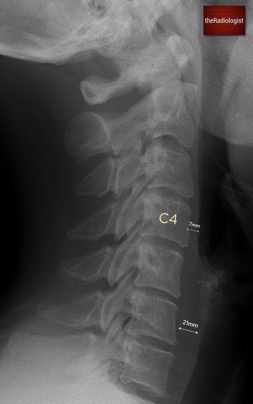
7 mm is the maximum prevertebral soft tissue thickness from C1-C4 whilst between C5-7 the maximal thickness is 21 mm
MEMORY AID
A simple rule to remember the key measurements on a lateral cervical spine X-ray is
3 × 7 = 21
3 mm: the maximum predental space in adults.
7 mm: the maximum prevertebral soft tissue thickness from C1–C4.
21 mm: the maximum prevertebral soft tissue thickness from C5–C7.
3. Alignment lines
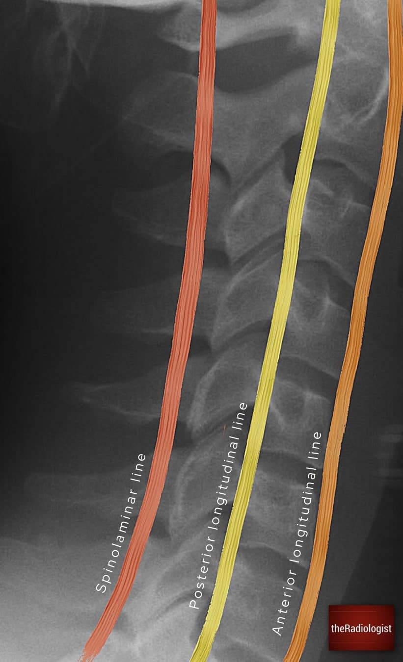
Three alignment lines should then be traced from top to bottom: the anterior longitudinal line (anterior cortices of the vertebrae), the posterior longitudinal line (posterior cortices of the vertebrae), and the spinolaminar line (join up points between the spinous processes and laminae). In a normal film, these appear as smooth, continuous arcs. Any disruption, step, or angulation suggests instability due to fracture, dislocation, or ligamentous injury. Because malalignment can be subtle, these lines should be followed carefully across the entire length of the cervical spine.
7 mm is the maximum prevertebral soft tissue thickness from C1-C4 whilst between C5-7 the maximal thickness is 21 mm
4. Atlanto-axial region
The upper cervical spine requires special attention. C1, the atlas, consists of anterior and posterior arches without a vertebral body. C2, the axis, has a vertebral body and the dens (odontoid process), which projects superiorly through the ring of C1.
The key measurement here is the predental space, also known as the atlantodental interval, which is the distance between the anterior arch of C1 and the anterior surface of the dens. In adults this should measure no more than 3 mm. Widening of this interval is a sign of instability, usually due to fracture or ligamentous disruption. Injuries are particularly common at C1–C2 and C6–C7, so these regions should always be interrogated carefully.
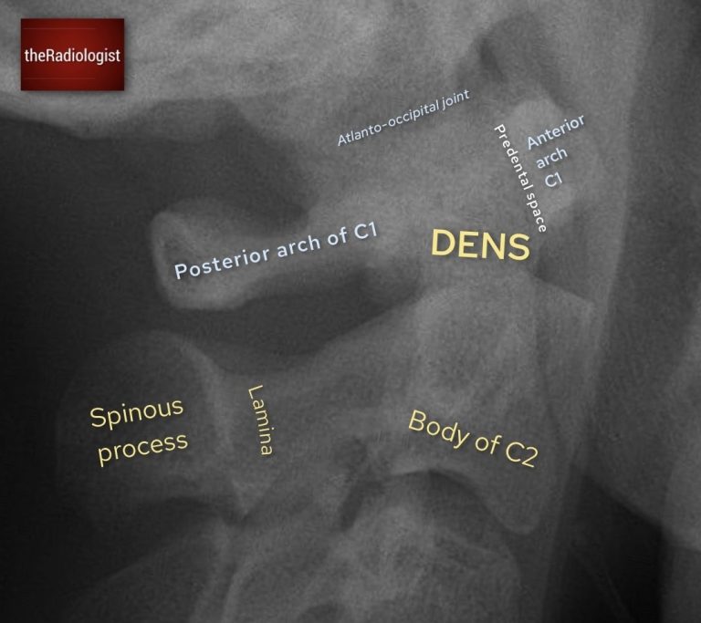
Outline the body of C2, the dens and the anterior and posterior arches of C1 as well as the predental space
5. Harris’ ring
Within the body of C2 lies an apparent outline known as Harris’ ring. This is formed by the superimposed shadows of the lateral masses of C2 around the dens. On a normal film, it appears as a smooth, continuous ring: although the inferior aspect is allowed to be slightly deficient. Otherwise any break, asymmetry, or irregularity suggests a fracture through the axis and should be regarded with suspicion.
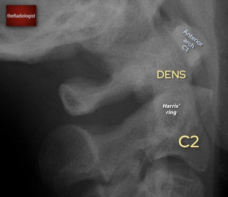
Identify a white ring within C2: this is Harris’ ring which is a composite shadow formed by the alteral masses of C2
KEY POINT
Harris’ ring is not a ‘real ring but a composite shadow. However ensuring it looks complete can help you identify a C2 fracture.
6. Spinous processes and interspinous distance
The spinous processes should be traced in sequence from C2 to C7. Each should be aligned in a straight line, with relatively uniform spacing. A focal increase in the interspinous distance indicates potential disruption of the posterior ligamentous complex and anterior cervical dislocation. Careful assessment of these intervals is particularly important in flexion-type injuries.
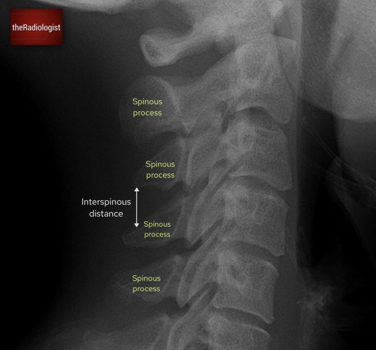
Look at the spinous processes and ensure the interspinous distance is relatively similar: more than 1.5 times difference can be significant
7. Vertebral bodies and disc spaces
Each vertebral body must then be outlined individually, checking for cortical breaks or loss of height that may represent compression fractures. The disc spaces should be reviewed for narrowing, widening, or the presence of small fragments, which may suggest avulsion. Consistency in height and smooth endplates are reassuring.
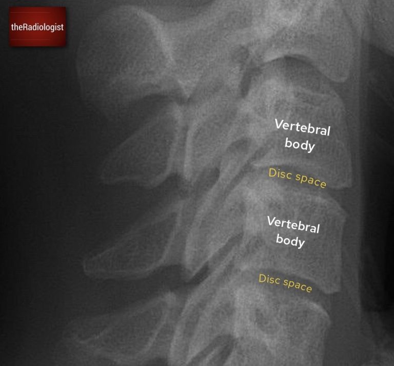
Ensure the vertebral body heights are maintained, there is no sign of fracture and the disc spaces are maintained.
8. Associated structures
Finally, do not neglect the surrounding structures. The occipital bone, mandible, and mastoid air cells should all be inspected, as associated fractures may be present in high-energy trauma. A fluid level in the mastoid air cells can indicate a basal skull fracture.

Review the surrounding structures such as the occipital bone, mandible and mastoid air cells.
Open mouth peg view review
The open mouth odontoid, or ‘peg’ view, is performed to assess the dens of C2 and the articulation between C1 and C2. It is a critical projection, as fractures and subluxations at this level can be unstable and easily missed.
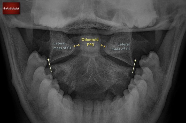
Annotated image of an open mouth peg view
1. Film adequacy
Confirm that the film is technically adequate. The teeth and occiput should not obscure the dens, and the lateral margins of C1 and C2 should be clearly visible. If the odontoid peg is not well seen, the view is non-diagnostic and should be repeated or further imaging obtained.
2. Alignment of lateral masses
This is a really important step: check that the lateral margins of C1 line up with those of C2. They should form a continuous vertical border on each side. Any offset suggests subluxation or fracture.
3. Symmetry around the dens
The odontoid peg should be equidistant from the lateral masses of C1. Asymmetry may reflect patient rotation, but can also represent true injury. If the lateral masses of C1 and C2 remain aligned and the only abnormality is unequal spacing between the dens and lateral masses, then the caue could be rotation rather than a true injury.
4. Integrity of the dens
Carefully inspect the cortex of the odontoid peg. It should appear smooth and continuous. Fractures may occur at the tip, through the body, or at the base of the dens. Subtle lucencies should not be dismissed, particularly in the trauma setting.
Be aware of artefacts that may mimic fracture. The ‘Mach effect’ produces false lines across the dens due to overlapping shadows. Superimposed teeth, tongue, or occipital bone can obscure detail or create apparent cortical breaks. Always interpret suspicious lines with caution and correlate with other views or cross-sectional imaging.
Long AP view review
The long AP cervical spine view complements the lateral and peg projections by allowing assessment of the spinous processes and interspinous spacing. Although less sensitive for fractures than the lateral film, it provides an important check for alignment and helps detect rotational or unilateral facet injuries.
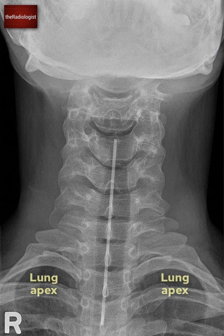
Annotated view of a long AP view
1. Film adequacy
Confirm that the film is centred and includes the cervical spine down to the cervicothoracic junction. The spinous processes should be clearly visible in the midline without significant overlap from the mandible or shoulders.
2. Spinous process alignment
The spinous processes should form a straight vertical line in the midline of the film. Any deviation away from this line may indicate rotation, malalignment, or more importantly, a unilateral facet joint dislocation. Even subtle offset should prompt careful reassessment with the lateral view or CT.
Beware of pitfalls: bifid spinous processes can create the illusion of misalignment, so this variant should not be mistaken for pathology.
3. Interspinous distance
Next, assess the spacing between adjacent spinous processes. These distances should be roughly equal throughout the cervical spine. A gap that is more than 50% wider than the one above or below is abnormal and strongly suggests anterior dislocation or posterior ligamentous injury.
Watch out if the neck is held in flexion due to spasm or positioning: the interspinous distances may appear falsely widened.
4. Lung apices
The AP view normally gives you a good view of the lung apices so ensure you don’t miss a pneumothorax, incidental Pancoast tumour or rib fracture.
Review area checklist
Let’s summarise the above: below you’ll find achecklist to help you when you next review a cervical spine X-Ray.
| Projection | Review area | Notes |
|---|---|---|
| Lateral | Adequacy | Is C7-T1 covered? |
| Prevertebral soft tissues | Ensure no larger than 7 mm between C1-4 and 21 mm between C5-7. | |
| Alignment | Follow the anterior and posterior vertebral lines as well as spinolaminar line. | |
| Atlanto-axial region | Atlantodental interval should be no more than 3 mm in adults. | |
| Harris’ ring | Look for this superimposed ring: a break implies fracture | |
| Spinous processes and interspinous distance | Trace the spinous processes and look for an increase in interspinous distance. | |
| Vertebral bodies and disc space | Look for loss of height and small fragments suggesting avulsion | |
| Associated structures | Assess the mandible, occipital bone and mastoid air cells. | |
| Open mouth peg view | Film adequacy | Ensure lateral masses visible and peg is well seen. |
| Alignment of lateral masses | Check the lateral border of the lateral masses of C1 and C2 line up. | |
| Symmetry around dens | Peg should be equidistant from lateral masses of C1 but beware rotation. | |
| Integrity of dens | Check the cortex of the peg but beware of Mach effect. | |
| Long AP view | Film adequacy | Ensure can see all of cervical spine and film is centred. |
| Spinous process alignment | Check all spinous processes form a straight line. | |
| Interspinous distances | Ensure spacing is relatively equal between spinous processes. | |
| Lung apices | Check for pneumothorax, Pancoast tumour and rib fracture. |